
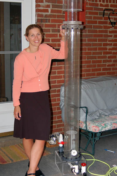
A 6′ Tall Recirculating Needle Wheel Protein Skimmer

In Late 2006 it became apparent that the tiny “Excalibur” protein skimmer on my reef tank was not sufficient to keep up with the bioload of my system. The original plan was to construct a 6′ tall Counter Current airstone skimmer.
After doing some research it became clear that airstone protein skimmers were very efficient but also required a significant amount of maintenance. The most suitable airstones are made of basswood or limewood and must be replaced rather often. To keep costs down, several people build DIY airstones. However, any way you look at it, the cost in time and money is significant. I needed to come up with a better solution. Aquaticecosystems sells fine pore airstones that can be cleaned but do not produce bubbles as fine as the wooden airstone. They also sell fine pore airstones but they require much more pressure than any reasonable linear piston pump can provide.
I quickly settled on a recirculating style needlewheel. I chose the Ocean Runner 3700 NW pump as the platform for the skimmer. The OR3700 is cheap and readily available. The only drawback is that the fittings are metric. The pump needed very little modification to run on the DIY skimmer. I chose to use standard North Amarican
This build log skips most of the basics, such as working with acrylic sheet goods and solvent cements. Please see the SUMP project if you need some pointers.
Lets get to the build shall we…
(click to enlarge)
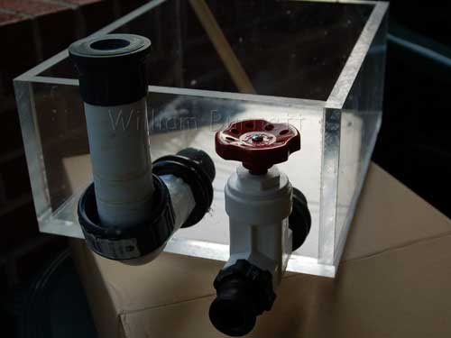
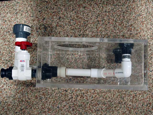
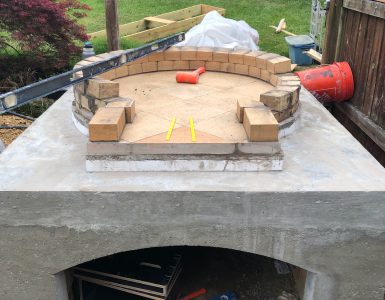
The first phase of the skimmer project was to build the base. The design of this skimmer is very simple, its a 6′ tall clear schedule 40 PVC (Harvel Plastics) body attached to a rectangular box. The box (the base) holds the recirculating pump intake and the dirty water intake from the aquarium, as well as the outlet to return clean water back to the aquarium. The photograph shows (top left of frame) the intake assembly for the recirculation pump and (bottom of frame) the gate valve and quick connect fitting that will serve as the system waste-to-sewer drain. The intake assembly is comprised of a 1″ bulkhead and standard PVC schedule 40 fittings glued to a schedule 80 PVC union. The other half of the union was epoxied to the Ocean Runner 3700 pump (more on this later). The box is shown without the acrylic top or the internal plumbing.
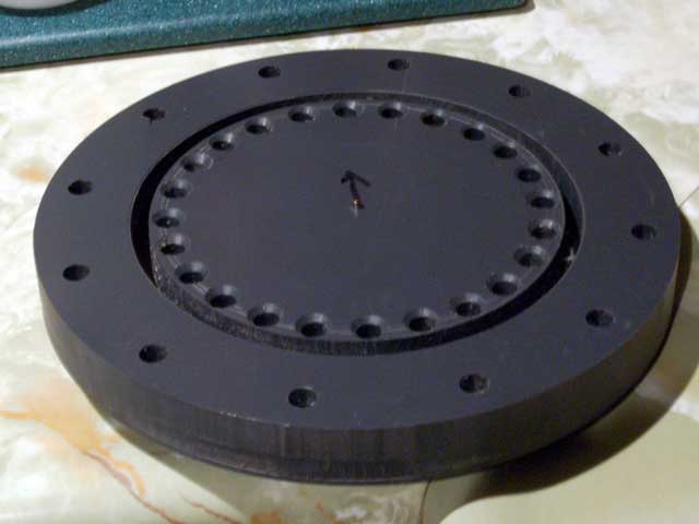
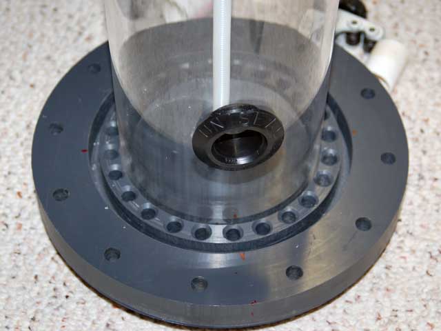
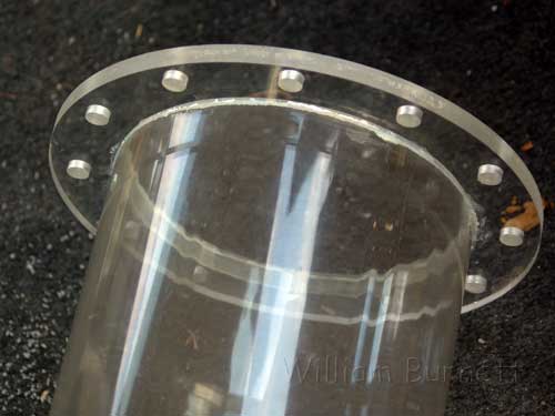
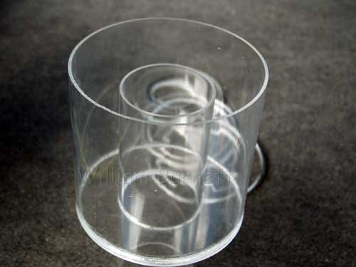
The next step was to build a flange to connect the body to the base. I purchased a 1″ thick piece of PVC sheet stock from McMaster-Carr and used a jasper jig and router to cut it into shape. The sheet stock was routed into a circle and then 2 1/2″ deep concentric grooves were routed into it. The center groove was sized to fit a piece of 4″ acrylic that would become the bubble chamber. The outer groove was sized to fit the 6″ schedule 40 PVC body. I drilled 24 1/2″ holes through the flange. These holes are between the baffle chamber and the body and allow water to recirculate into the base from the skimmer body. I also drilled 12 holes around the outer circumference to allow the flange to be attached to the base.
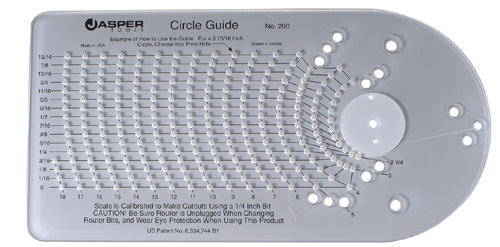

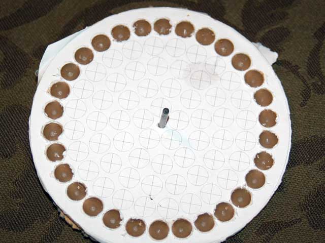
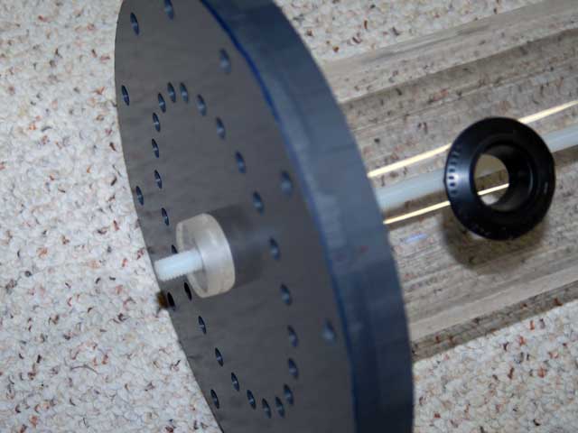
I used heavily modified ghostscript program originally written by MarkS (from ReefCentral) to print the desired layouts for the flanges and holes. I would post the code but seem to have misplaced it! The paper patterns were attached to the parts with spray adhesive prior to drilling. I built a small plywood indexing jig and used the drill press to ensure that all of the holes landed on the same circumference and had uniform spacing. The photo to the left is an example of one such pattern (in this case used for the acrylic baffle plate). When drilling mounting holes in a flange, even a tiny error can easily create flanges that do not line up. It is very important to be precise when drilling holes for flange mounting. Many a DIY flange only fits (where the holes line up correctly) in one position! Use a jig and measure three times!
(click to enlarge)
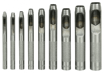
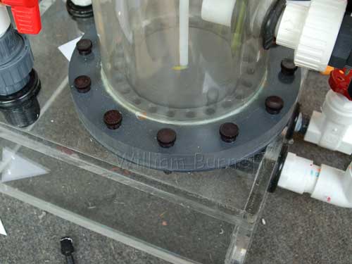
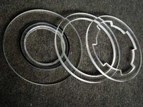
The acrylic box top was cut and drilled to match the hole pattern of the flange. I used a thin piece of neoprene rubber to fabricate the gasket. The flange was clamped to the neoprene and then a hollow punch set was used to pierce the gasket. The punch set came from Harbor Freight. The mounting holes in the box top were tapped to accept 1/2″ knurled nylon bolts (more on this later). I opted to use the gasket instead of an o-ring. The o-ring may have been easier to work with and required less pressure to form a tight seal. I had the neoprene on hand and forgot to order o-ring stock with the McMaster order.
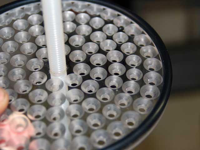
I was not sure how the bubble plate would work, therefore, I attached it and the bubble chamber to the flange with a piece of nylon all-thread and a DIY acrylic retaining nut. The lid of the bubble plate was routed to accept an EPDM O-ring. In this way, it would be possible to try different bubble plate configurations or remove the baffle chamber altogether. The O-ring prevents bubbles from leaking around the lid. The bubble plate was drilled with 5/16″ holes packed as densely as they could be fit. I used a single fluted countersink bit to give the holes a smooth shape and allow the bubbles to flow through with as little turbulence as possible. The bubble chamber was connected to the output port of the pump via a piece of 1″ PVC pipe installed through Uni-Seals fitted in the bubble chamber and body walls.
(click to enlarge)
The body was set into the groove on the flange and 2-part plastic epoxy was used to permanently connect the two. I had considered using a heavy bodied PVC solvent cement, but the tolerances of the routed groove were not close enough to ensure a competent bond. Another option was to use a plastic welder, however, the harbor freight model did not get good reviews and I was not prepared to spend the extra cash on a better model. In the end, the epoxy worked very well.
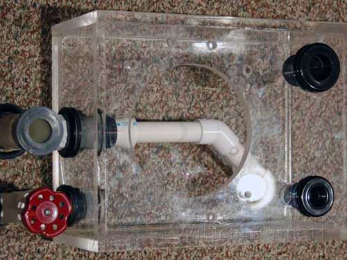
The plumbing was very straightforward and contained almost entirely in the skimmer base. Water from the aquarium enters the skimmer through a bulkhead in the base. It is directed towards the pumps intake via a piece of 3/4″ PVC pipe. A DIY PVC bell-shaped fitting was fabricated and attached to to the pumps intake bulkhead. The tank water is directed into this intake bell, but there is a gap between the bell and feed plumbing. This gap allows the pump to also draw in some water from the skimmer body. In this way I was able to ensure that all of the new water from the tank would be guaranteed to find its way into the needle wheel and skimmer body instead of bypassing the pump and flowing to the output pipe. The photo to the left shows the gap that allows the pump to intake all of the fresh feed water as well as recirculated water from the skimmer body. The 3/4″ intake bulkhead is shown on the top of the skimmer base along side the 1″ return bulkhead.


(click to enlarge)
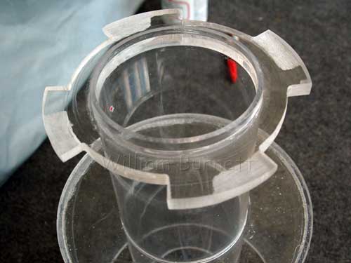
The top of the skimmer body was fitted with an acrylic flange set. One half of the flange was epoxied to the PVC skimmer body and the other half was attached to a thermoformed transition cone. As with the base flange, the upper flange set utilizes a DIY gasket made of neoprene. Nylon thumbscrews are used to secure the flange pieces together. The flange set allows the transition cone to be removed so that the skimmer body can be cleaned or the bubble plate be changed. I had considered building the skimmer on (3) 2 foot tall sections, each with a similar flange set. This would have allowed the skimmer to be easily moved or changed. In the end, it was too much work.
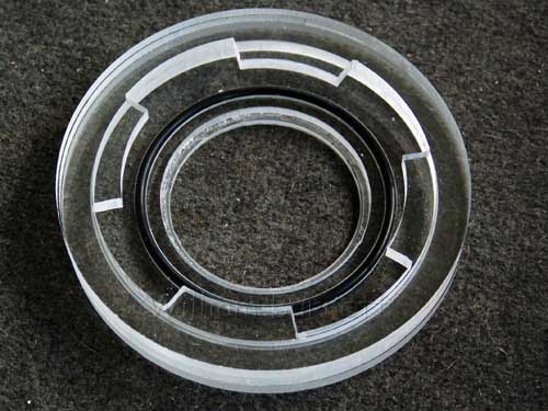
The riser tube and collection cup were constructed as a single integrated unit designed to attach to the upper flange via a DIY twistlock fitting. This allowed the neck/riser to be one smooth tube uninterrupted by a joint. The twistlock flange was constructed from three 1/2″ thick acrylic discs. The ramped portions of the male flange were hand sanded. The patterns for the neck pieces were constructed using a compass and paper, as I did not have the patience to use CAD software for something so small. The completed assembly was solvent welded to the top of the transition cone (neck) to finish the upper half of the top flange.
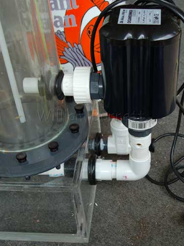
Air is injected into the intake side of the Ocean Runner pump. The injection point is a threaded John Guest quick connect fitting that is tapped into the intake just below the union fitting. Air is provided by an Alita AL-15 linear piston air pump.
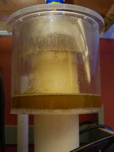
The final result was a very functional protein skimmer that is still in use today. The collection cup holds over a gallon of skimmate and is emptied once a week. The adjustment of the system has proved to be very easy and forgiving. An optical sensor will be tied to the collection cup in the near future. The sensor will act as a fail-safe measure in the event that the cup begins to overflow. Future plans also involve replacing the OR3700 with an Eheim needle wheel. I have heard very good things about the Eheim NW pumps. The OR is too noisy for my taste and sometimes fails to start after a power outage. Bubble size is fine, but the pump chokes on anything over about 25 SCFH of air and the bubbles become somewhat larger at anything above 21 SCFH.
To view more photographs of this project, please see DIY Needle Wheel Skimmer Gallery.
-BeanAnimal

Add comment