
Every aquarium forum is full of electrical questions and opinionated answers. As with most of the articles here at BeanAnimal.com, I will attempt shed some light (no pun) on the subject from a fact based perspective. Too many times, electrical questions are answered poorly based on the opinion of a well meaning but misinformed DIYer. We will look at a multitude of subjects and try to cover most of the common questions and concepts that a DIYer will run into.
Disclaimer
I will put this very bluntly. You should enlist the expertise of a fully licensed electrician before working with the electrical system of your home, or working on or building projects that will plug into that electrical system. The information provided here is for entertainment purposes only, use it at your own risk! If you do not fully understand what you are doing you could easily hurt or kill yourself or somebody else!!! Electricians can read too! If you need help, show your electrician this page, he (she) will be able to implement some of these ideas for your system!
The Basics
Having a basic understanding of our electrical system is important if you wish to undertake DIY projects. Most of our homes are wired with what is called a split-phase (3 wire) system, that is, the transformer supplying your home has a single-phase input (the primary winding). The output (secondary winding) is center-tapped. The center tap is connected to neutral (the ground). Phase to neutral voltage is 120 V on both sides of the center tap and 240 V between the two hot conductors. The graphic below illustrates this stepdown transformer and how your household voltage is derived from it.
We end up with 240 V service that is split into (2) 120 V conductors that are 180° out of phase with respect to each other. Small appliances and lighting fixtures can be connected between the NEUTRAL and one of the HOT conductors, giving the device 120 Volts. Larger appliances are designed to be connected between both HOT legs, giving them 240 Volts to work with.
So we now know that our electricity is delivered in the form of a true sine wave and that it comes in on two hot wires that have an RMS voltage of 120 Volts each when a meter is placed between either and the Neutral or Ground. We also know that if a meter is placed between the two hot legs we get a reading of 240 Volts RMS. Why would we want to have two different voltages in our homes? To answer that question, we will need to touch on the basics of a Law that governs everything electrical. Read on…
OHM’S LAW
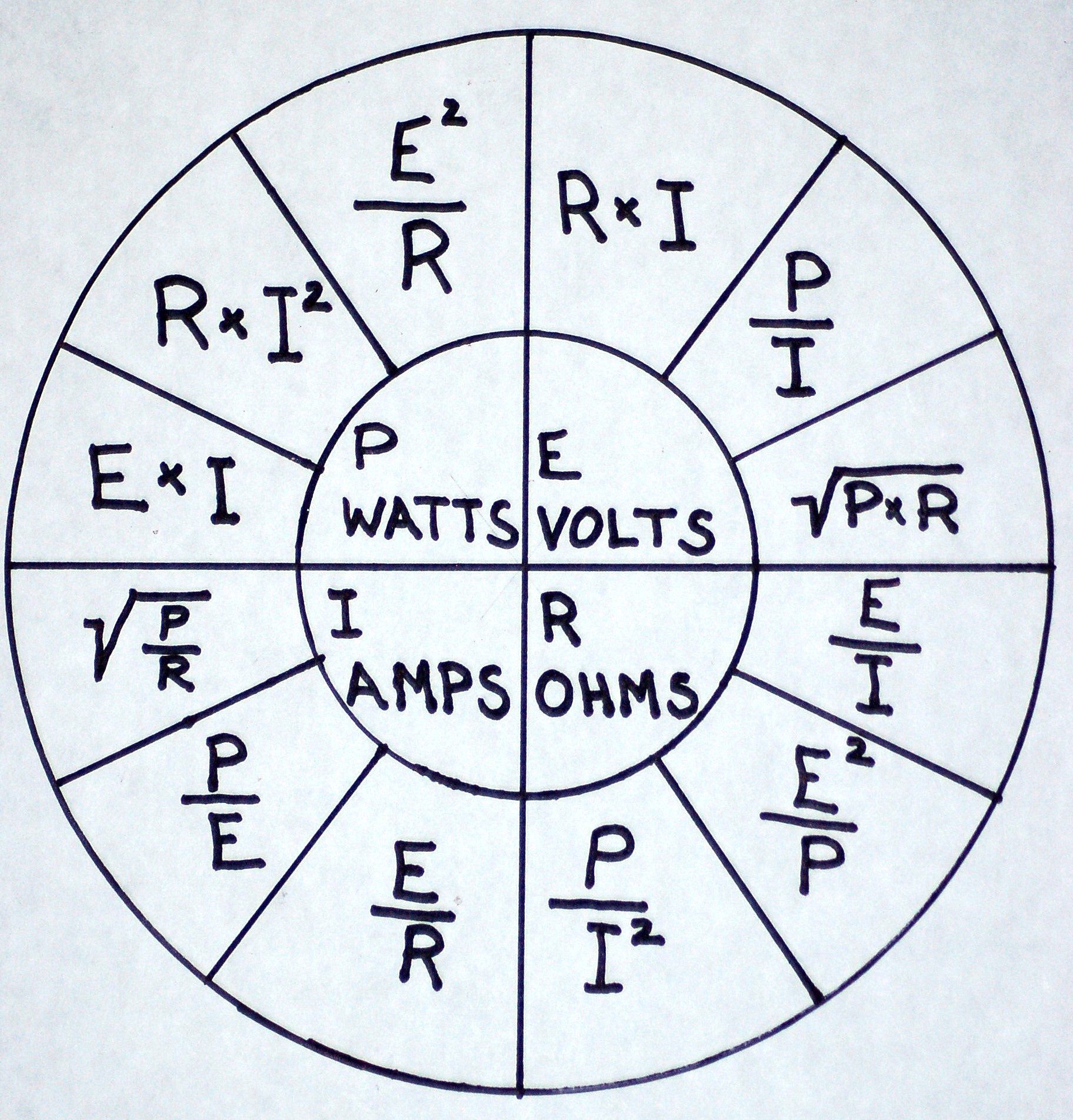
Ohm’s law governs everything electrical. Having a basic grasp of Ohm’s law will open the door to understanding electrical systems. The intent of this article is not to give an exhaustive lesson on such things, but rather, to give a basic overview of electricity as it relates to our hobby. With a basic understanding of these concepts you can work safer and with more confidence about your projects. If you click on the image to the left you will be presented with what is called the Ohm’s wheel. It is a graphical representation of all of the formulas that make up Ohm’s law. Don’t be discouraged, it is much simpler than it looks. Knowing two basic equations and a few simple concepts will fill in all of the gaps.
I – Current in AMPS. This is the basis for everything else. 1 Ampere is equivalent to 6.28 billion billion electrons per second passing a given point in a wire. Ponder that one for a moment! Pure physicists may argue a bit about the way I have presented this, but you get the point, we are counting electrons moving past a point in one second.
E – Potential in VOLTS. E stands for Electromotive force. It is not uncommon for people to use V instead of E. The VOLTS are what pushes the electrons.
R – Resistance in OHMS. R stands for Resistance. The RESISTANCE is what tries to stop the electrons from being pushed down the wire.
E and R are derived from I. Very simply put, One volt is the amount of electromotive force required to force one amp to flow through one ohm of resistance. With that we can build a very simple mathematical equation. VOLTS = AMPS × OHMS or properly: E = I × R
P – Power in WATTS. Power is the amount of work done or energy transferred per unit of time.
WATTS = VOLTS × AMPS or properly: P = E × I
We can think of VOLTS as the pressure that pushes electricity through the wire and we can think of AMPS as the amount of electricity that flows through the wire. OHMS can be thought of as the restrictions in the wire that keep the VOLTS from pushing the AMPS though the wire. We can compare this to a simple water pump setup. The water pump produces pressure that pushes water through a pipe. The larger the pump, the more pressure it can produce to overcome the restrictions in the pipe and therefore pump more water through the pipe.
If you look back at the Ohm’s wheel, you will notice that each formula is derived from either E = I × R or P = E × I
Knowing that little piece of information is critical if you want to work with electricity or electronics at any DIY level. Furthermore, knowing any two will allow us to solve for the third!
So why do we have 120V and 240V in our homes? Using Ohm’s law, we can see that doubling the voltage reduces the current by half for the same amount of power!
Lets take a clothes dryer as an example. The typical electric clothes dryer is rated at about 4000 watts. Using Ohm’s law:
4000 Watts ÷ 120 Volts = 33.3 Amps
-or-
4000 Watts ÷ 240 Volts = 16.6 Amps
What is the advantage? Very simply, because halved the current by doubling the voltage, we can use a smaller circuit breaker and smaller gauge wire to carry the smaller current. This is safer and more efficient!
Yes, more efficient! Heat causes resistance and resistance causes heat. The more current that you try to push over a wire, the hotter the wire will become. The hotter the wire becomes, the more it will resist the flow of electrons! So lowering the current also lowers the resistance and increases the efficiency. The advantage in your home may be very small, if at all relevant. In large industry the saving most certainly add up.
240 Volt Equipment
It should be noted that many vendors offer 240 Volt ballasts and pumps. It is against the NEC and many local codes to use 240 Volt lighting fixtures inside of a home. It is also not the ideal scenario when dealing with water. The 240 Volt pumps are suitable but there is little real world advantage to using them in a residential setting. Most of the pumps in our fraction horsepower models that draw very little current.
3 Phase Equipment
It is becoming rather common for technically inclined DIYers to build wave makers that use 3-phase fractional horsepower motors and programmable 3-phase converters. This is a complex subject and beyond the scope of this primer. Look for an upcoming DIY project here at beananimal.com!
CIRCUIT BREAKERS
A circuit breaker is a device that automaticaly intterupts the current flow in a circuit if a preset amount of current flow is exceeded. The circuit breaker is designed to protect the circuit from damage due to a short circuit or overload. The circuit breaker IS NOT designed to protect YOU the human from shock or *electrocution.
Circuit breaker sizing is confusing for many DIYers. Put simply, the circuit breaker must be sized to protect the smallest run of wire in the branch circuit. 12 Gauge wire is rated to be protected by a 20A circuit breaker and 14 Gauge wire is rated to be protected by a 15A circuit breaker. You CAN NOT simply replace a 15A breaker with a 20A model because you need more capacity. You MUST ensure that the entire circuit is wired with #12 wire before doing so!
Circuit breakers are only to be loaded to 80% of their rated capacity! If you load them past that point, you will experience nuisance tripping and possibly an eventual weakening of the breakers trip mechanism (causing more nuisance tripping). We can use Ohm’s law to show exactly what this is true. We will use P = E × I
20 Amps @ 120 Volts = 2400 Watts
2400 Watts – 20% = 1920 Watts
15 Amps @ 120 Volts = 1800 Watts
1800 Watts – 20% = 1440 Watts
So, using Ohm’s law we know that we should not load a 20A breaker past about 1900 Watts and a 15A breaker should not be loaded much past 1400 watts. Most equipment will have a wattage rating on the tag or nameplate. When calculating the load used by pumps and ballasts it is good to use 2-3 times the rating listed on the nameplate. Pumps and ballasts use MUCH more than their rated power during start-up. This can easily push a heavily loaded circuit into the red zone and cause a trip when you least expect it.
*Point of interest in the misinformation battle – The word ELECTROCUTION means DEATH BY ELECTRIC SHOCK and is commonly and INCORRECTLY used to describe the act of being shocked!
Nobody lives to say “Wow I just got Electrocuted”
With that in mind, we move to the next topic….
GFCI WHY?
A Ground Fault Circuit Interrupter (GFCI) is a device designed to protect against electric shock. The GFCI operates by sensing the difference between the currents in the Hot and Neutral conductors. Under normal conditions, these should be equal. If a person should come in contact with the live (HOT) wire and a path to ground, current would begin to flow through the body and therefore create in imbalance with the Neutral conductors current. The GFCI senses this imbalance (uneven current) and trips, cutting off power to the load side of the GFCI and protecting the person from shock.
An aquarium is the perfect place for a GFCI. Imagine a heater or submersible pump that has allowed water to leak into the electrical components. The Hot wire is now exposed to the tank water. When you place your hand in the water you are in essence touching the hot wire. If any other part of your body is in contact with a grounded object (reflectors, equipment, concrete floors, etc), current will begin to flow through your body! This can easily be a deadly situation and why a GFCI is an essential piece of equipment. A grounding probe added to the system can enhance the level of protection offered by a GFCI, this will be discussed in the grounding probe section of this article.
It is very important to understand that a GFCI does NOT protect against ungrounded shocks! That is, if a person contacts the HOT and NEUTRAL conductors, the current will flow through the body but still show as balanced to the GFCI. In this scenario, the body has become part of the load!
Many reefers incorporate a single GFCI into their setups and then plug all of their equipment into it. In a similar fashion, some reefers replace the standard circuit breaker in the service panel with a GFCI circuit breaker. A single faulting piece of equipment (or a nuisance trip) will result in loss of power to all of the equipment connected to the GFCI (or circuit in the case of a GFCI breaker). Both GFCI receptacles and GFCI circuit breakers are also susceptible to nuisance tripping. Ballast and motor loads create a complex signature that sometimes confuses GFCIs into thinking a fault has occurred.
Proper GFCI Daisy Chain Wiring
It is a good idea to separate important equipment among multiple GFCIs. In doing so, a single faulting piece of equipment (or nuisance trip) will only result in an isolated outage instead of a tank wide shutdown. You CAN NOT daisy chain GFCI receptacles by connecting a GFCI in series with the LOAD terminals of another GFCI. They will not operate as expected and will certainly cause problems. However, you can safely wire GFCI receptacles in parallel! Parallel GFCI receptacles will operate as expected when wired in parallel. Click on the schematic drawing to the left to see an example. The drawing depicts three GFCI receptacles wired in parallel. The 3rd unit has a standard (slave) receptacle wired to its load terminals. The standard receptacle is protected by GFCI #3. Slave receptacles (also know as downstream receptacles) can be added to any of the GFCI units and multiple GFCI units can be paralleled. The use of a ground probe is recommended and will be covered later in this article. Protect yourself and your family, implement GFCI protection on your tank!
AFCI WHY NOT?
Arc Fault Circuit Interrupters are designed to detect the electrical signature caused by electricity arcing someplace in the circuit. If arcing is detected, the AFCI breaker trips and removes power from the circuit. At first glance the AFCI appears to be a perfect candidate for fish tanks. Where there is water and electricity, there is a significant chance of arcing type fires. The problem is that AFCI breakers have a well deserved bad reputation for nuisance tripping when posed with a complex load such as a motor or ballast. An AFCI would add significant safety to a fish tank setup, but would also expose the livestock to a much higher greater risk of nuisance induced power outages. Most AFCI breakers also incorporate a GFCI into the device. A single GFCI used to power your tank (as mentioned above) is not a good idea. If you do not use AFCI circuit breakers (or the newer AFCI receptacles) then please take the precautions to prevent arcing type fires. That means taking precautions to protect power strips and other devices that will be exposed to moisture, drips and salt creep.
POWER STRIPS
A power strip can be a very dangerous thing if not properly selected and cared for. Many of us take them for granted and throw them under the stand with little thought to the danger they pose. You should select a power strip that has individual simplex receptacles instead of a molded plastic case. The individual receptacles have much better contacts inside and they do not melt as easily as the molded plastic variety. The outlet strip should be placed in such a manner that water can not splash or drip into it. All of the cords should have drip loops so that water running down the cord does not find its way into the receptacles. Unused receptacles should be covered with childproof plugs, as this will keep out the moisture and salt creep. The blades on the plugs should fit tightly into the receptacle. A loose fit is asking for an arcing fire. Loose fitting connections will allow the metal blades and leafs to corrode and eventually cause arcing due to the increased resistance created by the corroded contacts.
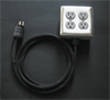
(click to enlarge)
I prefer to build my own power snakes using PVC or metal 4×4 gang boxes and commercial/hospital grade receptacles and plugs. Commercial and hospital grade receptacles have tighter leafs (contacts) and provide a much safer, more reliable connection that is less prone to corrosion and arcing due to loose fitting plug blades. Spring loaded outdoor covers or bubble style covers can also be added for moisture and drop protection. Plastic “child safety” covers should be plugged into any unused receptacles to help prevent corrosion of the leafs and/or arcing.
Please see my MUST READ power strip article for more information about power strips and their construction and dangers.
GROUND PROBES
A grounding probe is a piece of metal (silver or titanium, to be reef safe) that connects the system’s water to the home’s electrical grounding conductor. Grounding probes are somewhat controversial in the hobby. The probe adds a degree of protection against electrical shock but at the same time may allow current to flow through the aquarium and its inhabitants. The following examples will help to illustrate the concepts presented here. When a person comes in contact with the water AND the ground
Example #1: A powerhead in the tank develops a hole in the insulation of the HOT wire. The powerhead is not plugged into a GFCI and there is no grounding probe. Because there is no path for current to flow, the powerhead operates normally. Nothing in the aquarium is exposed to current flow. When a person comes in contact with the water AND the ground, then current will start to flow through that person. Because there is no GFCI to sense the imbalance, the person will receive a serious electrical shock and possibly be electrocuted! It should be very clear that a GFCI is a MUST HAVE piece of safety equipment!
Example #2: A powerhead in the tank develops a hole in the insulation of the HOT wire. The powerhead is not plugged into a GFCI and there is a ground probe. Because there is a path for current to flow, the inhabitants of the tank are exposed to electric current. Furthermore, when a person comes in contact with the water AND the ground, then current will start to flow through that person. Because there is no GFCI to sense the imbalance, the person will receive a serious electrical shock and possibly be electrocuted! It should be very clear that a grounding probe used WITHOUT a GFCI is very dangerous proposition.
Example #3: A powerhead in the tank develops a hole in the insulation of the HOT wire. The powerhead is plugged into a GFCI but there is no grounding probe. Because there is no path for the current to take, no current flows and the pump operates normally. Nothing in the aquarium is exposed to current flow. When a person comes in contact with the water AND the ground, then current will start flow through that person. The GFCI will sense the leak and trip, preventing serious electric shock.
Example #4: A powerhead in the tank develops a hole in the insulation of the HOT wire. The powerhead is plugged into a GFCI and there IS a grounding probe. As soon as the HOT wire is exposed, current will begin to flow through the tank water to the grounding probe. The GFCI will register this leak and trip.
There are plenty of other scenarios to look at. What happens when both the HOT and NEUTRAL (or ground) of a piece of equipment are both exposed underwater? With or without a GFCI, current will flow locally from the HOT to the NEUTRAL (or ground). The GFCI (if in place) will NOT trip because there is no current imbalance. The tanks inhabitants will not likely be aware of the current flow either. Placing a hand in the tank could provide a nasty shock! A grounding probe in conjunction with a GFCI would prevent this by causing the current to flow to the probe, and thus tripping the GFCI. The same holds true if two different pieces of equipment develop small leaks, one HOT and the other Neutral. The probe and GFCI combination would allow current to flow to the probe, subsequently causing the GFCI to trip.
Using a ground probe without GFCI protection on all of the submerged (or exposed) equipment creates a dangerous situation for the tank’s inhabitants and humans exposed to that tank. A ground probe must always be used with GFCI protection!
BALLAST WIRING
Metal Halide and Fluorescent retrofit and DIY projects are very popular and can offer a substantial savings over OEM fixtures. However, care must be taken when working with the load side of a ballast. Depending on the ballast type, output voltages can easily reach several hundred volts. The wire gauge and length determine the amount of current it can carry, but the insulation is what determines its safe operating voltage. Ballast to bulb wiring MUST be at rated for at least 600 Volts. If you are unsure of the voltage rating of the wire or cable, do not use it!
Wire gauge is determined by the lamp current and lamp type. Put simply, wire gauge for probe start bulbs and ballast combinations is determined by the bulb current only. The following table (taken from Venture Lighting) lists the common singled ended bulbs and ballasts used in the aquarium hobby. As you can see #18 wire is suitable for just about any application that an aquarist would need. 600V #18 wire can be hard to find in small quantities and therefore, #14 (slightly larger) may be used in its place.
Pulse start ballasts must be located within 3-5 feet of the lamp. The further the lamp is from the ignitor, the more the starting pulses are attenuated and the greater the chances are that the bulb will not fire. Some pulse start ballasts may come with long rage ignitors. It is also possible to move the ignitor to within 3 feet of the bulb, placing the long wire run between the ballast and ignitor. Check with the ballast manufacturer before attempting this! Please see the next section for a discussion of the proper wire and cable types.
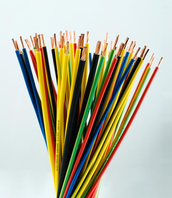
WIRE TYPES
There are dozens of wire types available to the DIYer. I have listed many of the common types below. We can break the wire down into a few basic types.
- Single-conductor wires used to pull through conduit or used as hook up wire inside devices
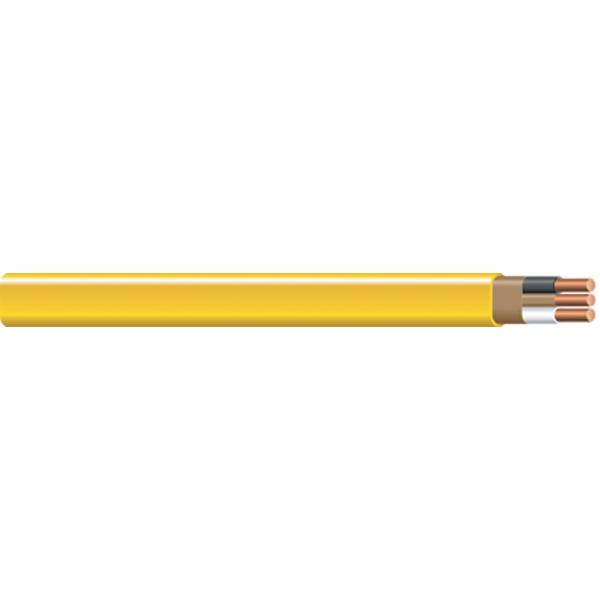
- Multi-conductor NM (Non Metalic sheathed) cable (a.k.a ROMEX) used to wire most residential buildings
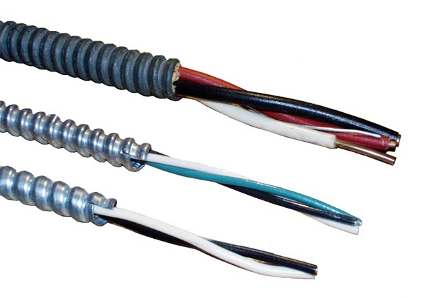
- Multi-conductor MC (Metalic Clad) cable used to wire most commercial structures.
- Multi-conductor flexible cable (cords) used to build extension cords and power cords for portable equipment and devices.
- Multi-conductor SE (Service Entrance)
So lets look at some of these wires and cables in a bit more detail. Keep in mind that the major differences are simply in the type and thickness of the insulation. The type and thickness of the insulation is what determines the wires voltage capacity and the suitable service environment that wire can be safely used in.
Single Conductor wire – There are dozens of different types of wire in this class. They differ mainly by the type of insulation and the conductor configuration. Types THHN or THW or THWN-2 are commonly used inside metal or PVC conduit to provide power to equipment and other devices. THHN #12 and #14 solid conductor wires are the most common types for use in 120V-240V residential and commercial applications. Many light fixtures and other high temperature devices will be wired internally with THWN-2 or similar high temperature wire stranded conductor wire. The stranded conductors allow more flexibility. Keep the insulation temperature ratings in mind when wiring a ballast or reflector/pendant. You will also find lower voltage or non-rated versions of single conductor wire at Radio Shack and other places. It may be referred to as “hook-up” wire or “test lead wire”, etc. Be careful when using this type of wire. It may not be suitable for the voltage or temperature rating of your project. Hook-up wire is typically used in small low voltage electronics projects.
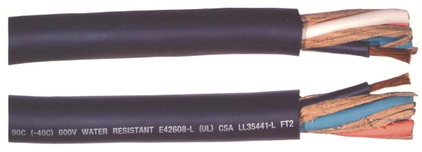
Multi Conductor cables – Again, there are dozens of types of cables in this class. You will commonly see type NM or NMB cable used to wire your home. These are the cables that feed the receptacles and lights in your home. This is likely the type of wire that you will use if you plan on adding one or more branch circuits to power your fish tank. Your home or business may have type MC cable instead of the type NM. The MC cable has a flexible steel cover that protects the wires inside of it. Your local code may require the use of MC cable instead of NM cable.
Flexible cords – These are “extension cord” type cables. You may here them referred to as SO, pronounced: /ˈɛsoʊ/ (“S-O”), cables. The actual letters in the cable type designate the type of jacket, insulation and duty rating. The common types are: SE, SEO, SEOO, SJ, SJE, SJEO, SJEOO, SJO, SJOO, SJT, SJTO, SJTOO, SO, and SOO. These are all hard-sservice or extra-hard-sservice flexible cords. With the “W-A” rating, they are also suitable for outdoor use. Again, each of the letters has meaning:
Service Entrance cables – These are the cables used to carry the power from the outside of your home, through the meter socket and into your fuse or breaker panel. There is not not much to say about this type of cable. If you DIY in this area, then you should be familiar with what is needed and how to safely proceed with the project.
The markings on the wire will tell you a lot about its purpose and ratings:
S: Hard Service Flexible Cord
SJ: Junior Hard Service Flexible Cord
E: Thermoplastic elastomer insulation
T: Thermoplastic insulation
R: Thermoset insulation (rubber or synthetic rubber)
X: Cross-linked synthetic polymer insulation
H: High temperature insulation (usually 75°C when dry or damp)
HH: Higher temperature insulation (usually 90°C when dry or damp)
W: Moisture resistant insulation (usually 60° when wet)
N: Nylon jacket
O: Jacket is oil resistant
OO: Jacket AND conductors are oil resistant
-2: High temperature and moisture resistance (90°C wet or dry)
Some common examples using the above nomenclature:
SJOOW: Junior hard service flexible cable that is oil and moisture resistant. This is basic black extension cord cable.
SOW:Hard service flexible cable that is oil and moisture resistant. Larger diameter (thicker) outer jacket than the SJ type cable. Used in heavy duty extension cords and equipment plugs.
THHN: Thermoplastic insulation higher temperature with a nylon jacket. This is what you will find inside most PVC and metal conduits as well as inside the NM cable.
THW-2: Thermoplastic insulated (tough insulation) high temperature and moisture resistant. Similar to above but with better moisture rating
THWN-2: Moisture and heat-resistant thermoplastic 90°C, wet and dry insulation rating May also be marked THHN. A cable marked only with THHN is not suitable for use in exposed conduits.
THHW: Same basic cable as above, but labeled slightly differently
RHW-2: Soft insulation (very flexible) high temperature and moisture resistant cable. You will find this inside many extension cords and equipment.
Wire Gauge
The wire gauge is simply the thickness of the current carrying portion of the wire. In general, the larger the conductor, the more current the wire can handle. Remember, the voltage rating of the wire is dictated by the type and thickness of the insulation, not the gauge (thickness) of the wire. In general 20A circuits are required to have #12 wire and 15A circuits are required to have #14 wire. You can find amapacity tables for different gauges and service conditions. However, be aware that the NEC (National Electric Code) does not follow the standard ampacity tables and instead mandates that much lower ampacity figures be used for safety and to accommodate diverse operating conditions.
Float Switches
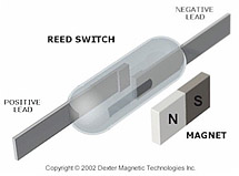
(click to enlarge)
There are many uses for float switches in the aquarium. A float switch consists of a tiny reed switch that is actuated by a magnet. The magnet is encapsulated in a floating ring or disc. As the ring rises or falls depending on the water level, the reed switch (shown to the left) is opened or closed by the magnet. The tiny nature of these switches makes them very susceptible to damge by voltage spikes and/or arcing caused by relays and other equipment. Simply put, trying to directly switch a 120V pump, heater or lighting fixture with a float switch is not advised. Not only is best to avoid putting 120V devices in contact with the water when possible, but switching the higher current and voltage directly with the switch is certain to shorten its useful life. A much better plan is to power the float switch with a low voltage supply and use a relay to switch the high voltage, high current devices. Please see the Electronics for the Reefer article for more details on float switch circuits.
Examples of common float switch styles
Timers
Content coming soon…
Dimmers
Content coming soon…
Sine Waves
As we learned in the beginig of this article, Alternating Current (AC) is delivered to your home in the form of a true sine wave. That is, the voltage swings continuously between a postive and negative value with respect to ground. Power is generated at the power plant by rotating an armature wound with copper wire through a magnetic field. Motors and other inductive loads rely on this smooth transition from positive to negative to operate properly.
Generators & UPS systems
Content coming soon…
Wire Nuts & Connections
Content coming soon….


Add comment