Home
Overflow
Articles
Projects
Other
Tools
About
Search
Search
Home
Overflow
Articles
Projects
Other
Tools
About
Search
Search
Search
Search
Category - Article
BeanAnimal's Reef
>
Article
Article
Biodiversity as a Reefing Buzzword
beananimal
2 weeks ago
10,026 views
Article
Why the Redfield Ratio Misleads Reef Keepers
beananimal
3 months ago
10,304 views
Article
PAR Meters – Illuminating or Not?
beananimal
June 29, 2024
10,795 views
Article
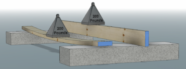
Beam Deflection – Easy Engineering for Aquarists
beananimal
October 20, 2023
11,704 views
The Solution is Dilution
beananimal
January 8, 2022
10,970 views
Article
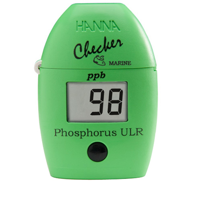
Hanna Checker HI-736 Opinion
beananimal
March 1, 2020
12,799 views
Article
Thermodynamics for the Reef Aquarist
beananimal
February 29, 2020
12,033 views
Article
Dorm Fridge Chillers?
beananimal
February 29, 2020
15,021 views
Article
HID Lighting – A Technical Overview
beananimal
February 29, 2020
13,831 views
Article
Aquarium Heaters: What you need to know!
beananimal
February 29, 2020
14,818 views
Load More
Home
Overflow
Articles
Projects
Other
Tools
About